Building a Solar-Powered Watering System for My Wife Using an ESP32
I’ve worked on quite a few projects involving Raspberry Pis, Arduinos, and ESP32 controllers over the years. Some were built to solve problems at work, while others started because I wanted to see whether I could make something work.
This particular project was for my wife: a solar-powered watering system that could automate watering without requiring a permanent electrical connection.
The concept was fairly straightforward. Use a solar panel to keep a battery charged, have a small microcontroller manage the watering schedule, and use an electrically controlled valve to turn the water on and off. Once programmed, the system would operate without someone having to remember to turn the water on every day.
Of course, coming up with the idea and actually putting everything together turned out to be two different things.
Choosing the Hardware
One of my original designs used a Raspberry Pi 3 B+. I already had experience with Raspberry Pi systems, so using one seemed like a reasonable approach. However, a full Raspberry Pi running Linux was more computer than this project really needed.
I’ve used Raspberry Pis for several projects over the years, including building a digital picture frame from an old laptop and later recreating it with a Raspberry Pi. For this project, however, the ESP32 made more sense because of its lower power requirements and built-in Wi-Fi.
But… this system would eventually sit outdoors, operate on battery power, and perform a relatively simple task. Keeping power consumption down was important, especially during periods when the solar panel wasn’t receiving much sunlight.
We also considered the Raspberry Pi Pico, but ultimately settled on an ESP32.
The ESP32 offered a good combination of processing power, programmable input and output pins, and built-in Wi-Fi. It didn’t require a full operating system, and it gave me flexibility for future additions, such as remote controls, monitoring, or integration with Home Assistant.
After choosing the controller, the rest of the hardware began to come together.
Components Used
| Component | Purpose |
|---|---|
| ESP32 development board | Main watering controller |
| SOLPERK 20W solar charging kit | Solar power generation and charging |
| DC HOUSE 12.8V 6Ah LiFePO₄ battery | Power storage |
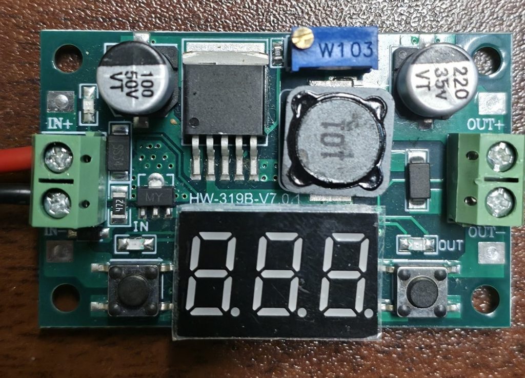
| LM2596 DC-DC buck converter | Reduces battery voltage to 5V |
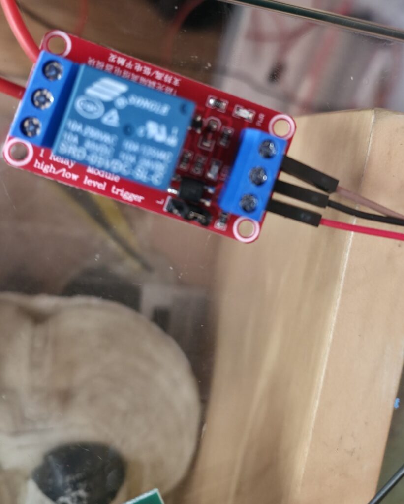
| AEDIKO 5V relay module | Electrical switching |
| U.S. Solid 3/4-inch motorized ball valve | Controls water flow |
| IP65 weather-resistant enclosure | Protects the electronics |
| 240-foot drip-irrigation kit | Distributes water to the plants |
| Wiring, connectors, and inline fuse | Electrical connections and protection |
The design uses a single watering zone, although additional zones could be considered in the future.
How My Solar-Powered Watering System Works
The electrical design begins with the solar panel. During daylight, the panel supplies power through a charge controller to replenish the battery. The battery is intended to power the electronics and water valve when needed.
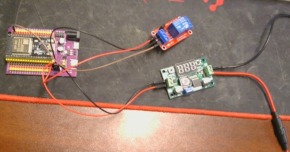
Because the ESP32 cannot be connected directly to the 12.8V battery, I used an LM2596 buck converter to bring the voltage down to 5V.
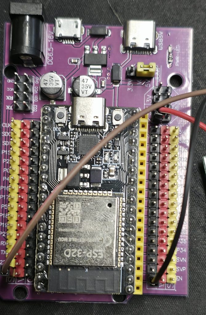
The ESP32 runs the watering logic and controls a relay. That relay is used in the valve-control circuit, allowing the controller to manage water flow without having to handle the valve’s power directly through one of its GPIO pins.
The watering system itself is based on drip irrigation, which delivers water through tubing rather than using a conventional lawn sprinkler.
Once installed, the goal is to have the controller handle scheduled watering automatically while still allowing manual operation when necessary.
Getting the ESP32 Running on Battery Power
One of the more important parts of this project was making sure the ESP32 could operate from the battery instead of relying on a USB connection.
We used the LM2596 converter for this purpose.
Before connecting the ESP32, I tested the converter’s output with a multimeter. The target was 5.00 volts, and the measurement came back right on the dot.
That was encouraging, but measuring the correct voltage and actually powering a device are two separate tests.
After disconnecting power and completing the connections, we powered the ESP32 through the converter. The controller started successfully using the 12.8V LiFePO₄ battery.
That confirmed an important part of the design: the battery and voltage converter could supply power to the ESP32.
There was still additional wiring to complete, including the relay and motorized water valve, but getting the controller running independently of USB was a significant step.
Wiring the Relay and Water Valve
The relay was another important part of the project.
The ESP32 operates with 3.3V logic and cannot directly power a 12V motorized valve. Instead, it sends a control signal to a relay module, which handles switching the separate valve circuit.
During development, we worked through the relay’s power, ground, and control connections. We also developed wiring layouts to show how the ESP32, LM2596 converter, relay, battery, and valve would connect.
One thing I wanted was a wiring diagram that was actually useful when assembling the hardware. Early diagrams weren’t particularly helpful, so we worked toward a clearer layout with labeled connections and color-coded wiring.
With several components operating at different voltages, accurate wiring is essential. Connecting 12V to the wrong ESP32 pin would be an expensive mistake for such a small project.
The design also required attention to circuit protection, including fused battery power and appropriate protection for the valve’s switching circuit.
Programming the Watering Controller
The ESP32 was selected for more than its electrical capabilities. I also wanted the watering system to be programmable and expandable.
The planned software features include automatic watering schedules, manual watering control, and an automatic shutoff so the valve doesn’t remain open indefinitely.
Accurate timekeeping is another consideration. With the ESP32’s Wi-Fi capability, the controller can be designed to synchronize its clock using Network Time Protocol (NTP).
We also discussed saving configuration settings so that a restart or temporary power interruption wouldn’t require reprogramming the entire system.
Eventually, I’d like to have a convenient way to manage the controller from a phone, potentially through a web interface or Home Assistant.
For now, the priority has been getting the hardware and basic controller operation working rather than adding every possible feature at once.
Why Solar Power?
The solar panel is what makes the project particularly interesting to me.
A conventional watering timer would certainly be easier to purchase and install. There are plenty of commercially available systems that do something similar.
But the objective here was to build our own system, understand how the components work together, and have the flexibility to make changes later.
The 20W solar panel and 12.8V battery were selected to provide a power source that wouldn’t require running electrical wiring to the installation location.
Whether that combination can sustain the system over long periods will depend on actual power consumption, solar exposure, weather, and how often the valve operates.
Those are things we won’t be able to evaluate properly until the system is deployed.
Current Status: Working, but Not Installed
As of November 2026, the project has reached the testing stage.
The ESP32 is our final controller, and the electronics have been tested successfully. We also confirmed that the battery could power the controller through the LM2596 converter.
However, the complete system has not been put into outdoor service.
The solar charging connection still needs to be completed, and the drip-irrigation equipment is sitting in a box until spring 2027.
That means I can’t yet report how well the battery performs over several days, how reliably the solar panel keeps it charged, or how the watering system handles an entire growing season.
Those will be part of the next phase.
What’s Next for Spring 2027?
When spring arrives, we’ll be able to install the watering equipment and test everything under actual operating conditions.
The remaining work includes completing the solar charging installation, mounting and protecting the electronics, laying out the drip-irrigation tubing, and testing the watering schedule with water flowing through the system.
I’ll also want to monitor battery performance and make sure the controller operates reliably through different weather conditions.
Additional features, including battery monitoring, soil moisture sensing, and Home Assistant integration, are possibilities for later versions.
For now, the electronics are working, the components are here, and the rest of the project can wait until spring.
There’s no point laying out 240 feet of irrigation tubing in November just to prove that I can.
This project isn’t finished, but it’s far enough along that the next step is getting it out of the workshop and into the yard.
Stay Tuned.